
User's Manual
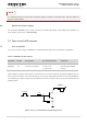

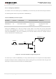

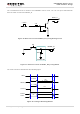
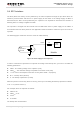
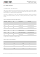
Table Of Contents
- About the Document
- Contents
- Table Index
- Figure Index
- 1 Introduction
- 2 Product Concept
- 3 Application Interface
- 3.1. General Description
- 3.2. Pin Assignment
- 3.3. Pin Description
- 3.4. Operating Modes
- 3.5. Power Saving
- 3.6. Power Supply
- 3.7. Turn on and off Scenarios
- 3.8. Reset the Module
- 3.9. RTC Interface
- 3.10. UART Interface
- 3.11. USIM Card Interface
- 3.12. USB Interface
- 3.13. PCM and I2C Interface
- 3.14. Network Status Indication
- 3.15. Operating Status Indication
- 4 Antenna Interface
- 5 Electrical, Reliability and Radio Characteristics
- 6 Mechanical Dimensions
- 7 Storage and Manufacturing
- 8 Appendix A Reference
- 9 Appendix B GPRS Coding Scheme
- 10 Appendix C GPRS Multi-slot Class
- 11 Appendix D EDGE Modulation and Coding Scheme

UMTS/HSPA Module Series
UG96 Hardware Design
UG96_Hardware_Design Confidential / Released 30 / 75
It is suggested that you should switch off power supply for module in abnormal state, and then switch on
power to restart module.
3.6.4. Monitor the Power Supply
The command AT+CBC can be used to monitor the VBAT_BB voltage value displayed in millivolt. For
more details, please refer to document [1].
3.7. Turn on and off Scenarios
3.7.1. Turn on Module
Turn on the module using the PWRKEY. The following table shows the pin definition of PWRKEY.
Table 7: PWRKEY Pin Description
Pin Name
Pin No.
Description
DC Characteristics
Comment
PWRKEY
15
Turn on the module.
V
IH
max=2.1V
V
IH
min=1.3V
V
IL
max=0.5V
Pull-up to VRTC
internally with 200kΩ
resistor.
When UG96 is in power down mode, it can be turned on to normal mode by driving the PWRKEY pin to a
low level at least 100ms. It is recommended to use an open drain/collector driver to control the PWRKEY.
The STATUS pin output a high level after UG96 is turned on. A simple reference circuit is illustrated in the
following figure.
Turn on pulse
PWRKEY
4.7K
47K
≥ 100ms
Figure 9: Turn on the Module Using Driving Circuit
NOTE