
User's Manual
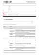
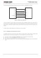
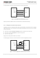
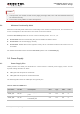
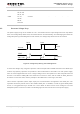
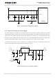
Table Of Contents
- About the Document
- Contents
- Table Index
- Figure Index
- 1 Introduction
- 2 Product Concept
- 3 Application Interface
- 3.1. General Description
- 3.2. Pin Assignment
- 3.3. Pin Description
- 3.4. Operating Modes
- 3.5. Power Saving
- 3.6. Power Supply
- 3.7. Turn on and off Scenarios
- 3.8. Reset the Module
- 3.9. RTC Interface
- 3.10. UART Interface
- 3.11. USIM Card Interface
- 3.12. USB Interface
- 3.13. PCM and I2C Interface
- 3.14. Network Status Indication
- 3.15. Operating Status Indication
- 4 Antenna Interface
- 5 Electrical, Reliability and Radio Characteristics
- 6 Mechanical Dimensions
- 7 Storage and Manufacturing
- 8 Appendix A Reference
- 9 Appendix B GPRS Coding Scheme
- 10 Appendix C GPRS Multi-slot Class
- 11 Appendix D EDGE Modulation and Coding Scheme

UMTS/HSPA Module Series
UG96 Hardware Design
UG96_Hardware_Design Confidential / Released 28 / 75
GND
3, 31, 48, 50
54, 55, 58,
59, 61, 62,
67~74,
79~82,
89~91,
100~102
Ground
-
-
-
-
3.6.2. Decrease Voltage Drop
The power supply range of the module is 3.3V~ 4.3V. Make sure the input voltage will never drop below
3.3V. If the voltage drops below 3.3V, the module will turn off automatically. The following figure shows the
voltage drop during transmitting burst in 2G network, the voltage drop will be less in 3G network.
< 400mV
Current
VBAT
≤ 2.0A
burst
burst
Min. 3.3V
Figure 6: Voltage Drop during Transmitting Burst
To decrease voltage drop, a bypass capacitor of about 100µF with low ESR should be used. Multi-layer
ceramic chip (MLCC) capacitor can provide the best combination of low ESR. The main power supply
from an external application has to be a single voltage source and splits into to two sub paths with star
structure. The width of VBAT_BB trace should be no less than 1mm, and the width of VBAT_RF trace
should be no less than 2mm, and the principle of the VBAT trace is the longer, the wider.
Three ceramic capacitors (100nF, 33pF, 10pF) are recommended to be applied to the VBAT pins. The
capacitors should be placed close to the UG96’s VBAT pins. In addition, in order to get a stable power
source, it is suggested that you should use a zener diode of which reverse zener voltage is 5.1V and
dissipation power is more than 0.5W. The following figure shows star structure of the power supply.