
User's Manual

UMTS/HSPA Module Series
UG95 Hardware Design
UG95_Hardware_Design Confidential / Released 48 / 67
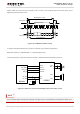
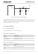
RF_ANT
R1 0R
C1
NM
C2
NM
Module
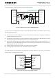
Figure 30: Reference Circuit of Antenna Interface
UG95 provides an RF antenna PAD for customer’s antenna connection. The RF trace in host PCB
connected to the module RF antenna pad should be micro-strip line or other types of RF trace, whose
characteristic impendence should be close to 50Ω. UG95 comes with grounding pads which are next to
the antenna pad in order to give a better grounding.
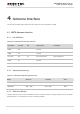
4.2. Antenna Installation
4.2.1. Antenna Requirement
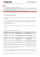
The following table shows the requirement on UMTS antenna.
Table 22: Antenna Cable Requirements
Type
Requirements
UMTS 850
Cable insertion loss <1dB
UMTS 1900/2100
Cable insertion loss <1.5dB
Table 23: Antenna Requirements
Type
Requirements
Frequency Range
UG95
UMTS Dual-band: 850/1900MHz.
VSWR
≤ 2