
User's Manual

UMTS/HSPA Module Series
UG95 Hardware Design
UG95_Hardware_Design Confidential / Released 41 / 67
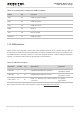
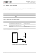
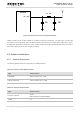
Table 14: Pin Description of Amphenol USIM Card Holder
Name
Pin
Function
VDD
C1
USIM card power supply.
RST
C2
USIM card reset.
CLK
C3
USIM card clock.
GND
C5
Ground.
VPP
C6
Not connected.
DATA I/O
C7
USIM card data.
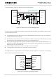
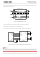
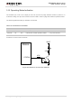
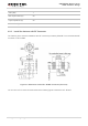
3.12. USB Interface
UG95 contains one integrated Universal Serial Bus (USB) transceiver which complies with the USB 2.0
specification and supports high speed (480 Mbps), full speed (12 Mbps) and low speed (1.5 Mbps) mode.
The USB interface is primarily used for AT command, data transmission, software debug and firmware
upgrade. The following table shows the pin definition of USB interface.
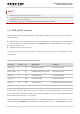
Table 15: USB Pin Description
Pin Name
Pin No. I/O
Description
Comment
USB_DP
9
IO
USB differential data bus (positive).
Require differential
impedance of 90Ω.
USB_DM
10
IO
USB differential data bus (minus).
Require differential
impedance of 90Ω.
USB_VBUS
8
PI
Used for detecting the USB interface
connected.
2.5~5.25V.
Typical 5.0V.
More details about the USB 2.0 specifications, please visit http://www.usb.org/home.