
User's Manual

UMTS/HSPA Module Series
UG95 Hardware Design
UG95_Hardware_Design Confidential / Released 37 / 67
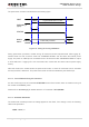
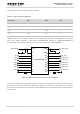
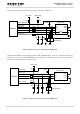
1. The module disables the hardware flow control by default. When hardware flow control is required,
RTS and CTS should be connected to the host. AT command AT+IFC=2,2 is used to enable
hardware flow control. AT command AT+IFC=0,0 is used to disable the hardware flow control. For
more details, please refer to document [1].
2. Rising edge on DTR will let the module exit from the data mode by default. It can be disabled by AT
commands. Refer to document [1] for details.
3. DCD is used as data mode indication. Refer to document [1] for details.
4. It is suggested to set USB_DP, USB_DM and USB_VBUS pins as test points and then place these
test points on the DTE for debug.
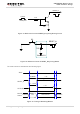
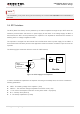
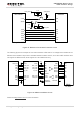
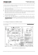
3.11. USIM Card Interface
3.11.1. USIM Card Application
The USIM card interface circuitry meets ETSI and IMT-2000 SIM interface requirements. Both 1.8V and
3.0V USIM cards are supported.
Table 12: Pin Definition of the USIM Interface
Pin Name
Pin No. I/O
Description
Comment
USIM_PRES
ENCE
42
DI
USIM card detection input.
1.8V power domain.
USIM_VDD
43
PO
Power supply for USIM card.
Either 1.8V or 3.0V is supported
by the module automatically.
USIM_RST
44
DO
Reset signal of USIM card.
USIM_DATA
45
IO
Data signal of USIM card.
Pull-up to USIM_VDD with 4.7k
resistor internally.
USIM_CLK
46
DO
Clock signal of USIM card.
USIM_GND
47
Specified ground for USIM
card.
NOTES