
User's Manual

UMTS/HSPA Module Series
UG95 Hardware Design
UG95_Hardware_Design Confidential / Released 36 / 67
MCU/ARM
/TXD
/RXD
VDD_EXT
4.7K
VCC_MCU
4.7K
4.7K
VDD_EXT
TXD
RXD
RTS
CTS
DTR
RI
/RTS
/CTS
GND
GPIO DCD
Module
GPIO
EINT
VDD_EXT
Voltage level: 5V
4.7K
GND
1nF
1nF
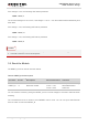
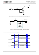
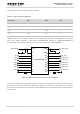
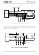
Figure 18: Reference Circuit with Transistor Circuit
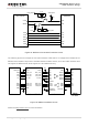
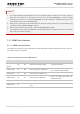
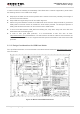
The following figure is an example of connection between UG95 and PC. A voltage level translator and a
RS-232 level translator chip must be inserted between module and PC, since the UART interface does
not support the RS-232 level, while support the 1.8V CMOS level only.
TXS0108EPWR
DCD_3.3V
RTS_3.3V
DTR_3.3V
RXD_3.3V
RI_3.3V
CTS_3.3V
TXD_3.3V
DCD
RTS
DTR
RXD
RI
CTS
TXD
DCD_1.8V
RTS_1.8V
DTR_1.8V
RXD_1.8V
RI_1.8V
CTS_1.8V
TXD_1.8V
VCCA
Module
GND GND
VDD_EXT VCCB
3.3V
DIN1
ROUT3
ROUT2
ROUT1
DIN4
DIN3
DIN2
DIN5
R1OUTB
FORCEON
/FORCEOFF
/INVALID
3.3V
DOUT1
DOUT2
DOUT3
DOUT4
DOUT5
RIN3
RIN2
RIN1
VCC GND
OE
SN65C3238
DB9M
PC side
DCD
RTS
DTR
TXD
RI
CTS
RXD
DSR
GND
1
2
3
4
5
6
7
8
9
Figure 19: RS232 Level Match Circuit
Please visit http://www.ti.com for more information.