
User's Manual

UMTS/HSPA Module Series
UG95 Hardware Design
UG95_Hardware_Design Confidential / Released 33 / 67
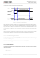
Use the RESET_N only when turning off the module by the command AT+QPOWD and the PWRDWN_N
pin failed.
3.9. RTC Interface
The RTC (Real Time Clock) can be powered by an external capacitor through the pin VRTC when the
module is powered down and there is no power supply for the VBAT. If the voltage supply at VBAT is
disconnected, the RTC can be powered by the capacitor. The capacitance determines the duration of
buffering when no voltage is applied to UG95.
The capacitor is charged from the internal LDO of UG95 when there is power supply for the VBAT. A
serial 1KΩ resistor had been placed on the application inside the module. It limits the input current of the
capacitor.
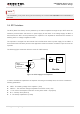
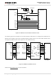
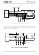
The following figure shows the reference circuit for VRTC backup.
Large
Capacitance
Capacitor
Module
RTC
Core
1K
VRTC
C
Figure 16: RTC Supply from Capacitor
In order to evaluate the capacitance of capacitor according to the backup time, we have to consider the
following parameters:
VRTC - The starting voltage of the capacitor. ( Volt)
VRTC
MIN
- The minimum voltage acceptable for the RTC circuit.( Volt)
I - The current consumption of the RTC circuitry when VBAT = 0.(Ampere)
B
Time
- Backup Time.(Second)
C - The backup capacitance. (Farad)
NOTE