
User's Manual

UMTS/HSPA Module Series
UG95 Hardware Design
UG95_Hardware_Design Confidential / Released 29 / 67
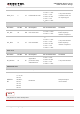
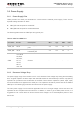
Table 8: PWRDWN_N Pin Description
Pin Name
Pin No.
Description
DC Characteristics
Comment
PWRDWN_N
16
Turn off the module.
V
IH
max = 2.1V
V
IH
min = 1.3V
V
IL
max = 0.5V
Pull-up to 1.8V internally
with 4.7kΩ resistor.
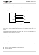
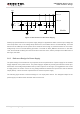
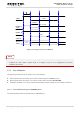
Driving the PWRDWN_N to a low level voltage at least 100ms, the module will execute power-down
procedure after PWRDWN_N is released. It is recommended to use an open drain/collector driver to
control the PWRDWN_N. You can monitor the level of the STATUS pin to judge whether the module is
turned off or not. The level of STATUS pin is low, after UG95 is turned off. A simple reference circuit is
illustrated in the following figure.
Turn off pulse
PWRDWN_N
4.7K
47K
≥ 100ms
Figure 10: Turn off the Module Using Driving Circuit
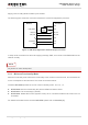
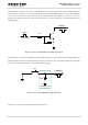
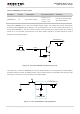
The other way to control the PWRDWN_N is using a button directly. A TVS component is indispensable to
be placed nearby the button for ESD protection. When pressing the key, electrostatic strike may generate
from finger. A reference circuit is showed in the following figure.
PWRDWN_N
S2
Close to S2
TVS
Figure 11: Turn off the Module Using Keystroke