
User's Manual

UMTS/HSPA Module Series
UG95 Hardware Design
UG95_Hardware_Design Confidential / Released 26 / 67
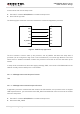
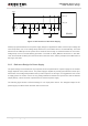
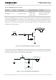
DC_IN
C1
C2
MIC29302WU U1
IN
OUT
EN
GND
ADJ
2 4
1
3
5
VBAT
100nF
C3
470uF
C4
100nF
R2
100K
47K
R3
470uF
470R
51K
R4
R1
1%
1%
MCU_POWER
_ON/OFF
47K
4.7K
R5
R6
Figure 6: Reference Circuit of Power Supply
It is suggested to disconnect power supply to turn off the module when the module is in abnormal state.
3.6.4. Monitor the Power Supply
You can use the AT+CBC command to monitor the VBAT_BB voltage value. For more details, please
refer to document [1].
3.7. Turn on and off Scenarios
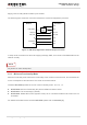
3.7.1. Turn on Module
Turn on the module using the PWRKEY. The following table shows the pin definition of PWRKEY.
Table 7: PWRKEY Pin Description
Pin Name
Pin No.
Description
DC Characteristics
Comment
PWRKEY
15
Turn on the module.
V
IH
max = 2.1V
V
IH
min = 1.3V
V
IL
max = 0.5V
Pull-up to 1.8V internally
with 200kΩ resistor.
NOTE