
User's Manual

UMTS/HSPA Module Series
UG95 Hardware Design
UG95_Hardware_Design Confidential / Released 17 / 67
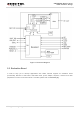
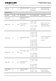
VDD_EXT
29
PO
Provide 1.8V for
external circuit.
Vnorm = 1.8V
I
O
max = 20mA
Power supply for
external GPIO’s pull up
circuits.
GND
3,31,48,
50,54,55,
58,59,61,
62,67~74,
79~82,
89~91,
100~102
Ground.
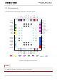
Turn On/Off
Pin Name
Pin No.
I/O
Description
DC Characteristics
Comment
PWRKEY
15
DI
Turn on the module.
R
PU
≈ 200kΩ
V
IH
max = 2.1V
V
IH
min = 1.3V
V
IL
max= 0.5V
Pull-up to 1.8V
internally.
Active low.
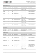
PWRDWN_N
16
DI
Turn off the module.
R
PU
≈ 4.7kΩ
V
IH
max = 2.1V
V
IH
min = 1.3V
V
IL
max = 0.5V
Pull-up to 1.8V
internally.
Active low.
RESET_N
17
DI
Reset the module.
R
PU
≈ 200kΩ
V
IH
max = 2.1V
V
IH
min = 1.3V
V
IL
max = 0.5V
Pull-up to 1.8V
internally.
Active low.
Status Indication
Pin Name
Pin No.
I/O
Description
DC Characteristics
Comment
STATUS
20
DO
Indicate the module
operating status.
V
OH
min =1.3V
V
OL
max = 0.5V
1.8V power domain.
NETLIGHT
21
DO
Indicate the module
network status.
V
OH
min = 1.3V
V
OL
max = 0.5V
1.8V power domain.
USB Interface
Pin Name
Pin No.
I/O
Description
DC Characteristics
Comment
USB_VBUS
8
PI
USB insert
detection.
Vmax = 5.25V
Vmin
= 2.5V
Vnorm = 5.0V
USB insert detection.
USB_DP
9
IO
USB differential data
bus.
Compliant with USB
2.0 standard
specification.
Require differential
impedance of 90Ω.