
User Manual

UMTS/HSDPA Module Series
UC15 Mini PCIe Hardware Design
UC15_Mini_PCIe_Hardware_Design Confidential / Released 26 / 40
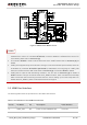
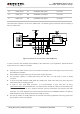
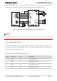
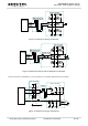
The following figure shows the reference design of PCM interface with external codec IC.
Figure 11: Reference Circuit of PCM Application with Audio Codec
It is recommended to reserve RC (R=22Ω, C=22pF) circuit on the PCM lines, especially for PCM_CLK.
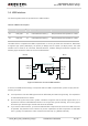
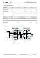
3.7.2. Analog Audio Interface
UC15 Mini PCIe Telematics version supports one differential input and output analog audio interface, and
this interface works as the default audio channel. The following tables show the pin definition and
characteristics of analog audio interface.
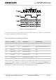
Table 11: Pin Definition of Analog Audio Interface
Pin No. Pin Name I/O Description
1 MICP AI Audio positive input.
3 MICN AI Audio negative input.
5 SPKP AO Audio positive output.
7 SPKN AO Audio negative output.
NOTE