
User Manual

UMTS/HSDPA Module Series
UC15 Mini PCIe Hardware Design
UC15_Mini_PCIe_Hardware_Design Confidential / Released 17 / 40
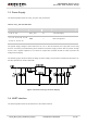
1. PCM and analog audio interface are only supported in Telematics version.
2. Keep all NC, reserved and unused pins unconnected.
3.2.2. Pin Assignment
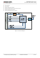
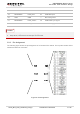
The following figure shows the pin assignment of UC15 Mini PCIe module. The top side contains UC15
module and antenna connectors.
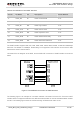
Figure 2: Pin Assignment
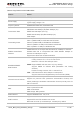
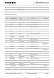
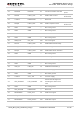
48 1.5V NC — —
49 RESERVED PCM_DIN* DI PCM data input
50 GND GND — Mini card ground
51 RESERVED PCM_SYNC* IO PCM frame sync signal
52 3.3Vaux VCC_3V3 PI 3.3V DC supply
NOTES