
User's Manual

UMTS/HSDPA Module Series
UC15 Hardware Design
UC15_Hardware_Design Confidential / Released 59 / 78
4.1.3. Reference Design
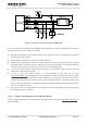
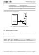
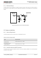
The RF interface has an impedance of 50Ω.The reference design of RF antenna is shown as below. It
should reserve a π-type matching circuit for better RF performance. The capacitors are not mounted by
default.
Figure 38: Reference Circuit of Antenna Interface
4.2. Antenna Installation
4.2.1. Antenna Requirement
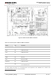
The following table shows the requirements on GSM/UMTS antenna.
Table 28: Antenna Requirements
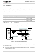
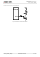
4.2.2. Install the Antenna with RF Connector
The following is the antenna installation with RF connector provided by HIROSE. The recommended RF
connector is UF.L-R-SMT.
Type Requirements
GSM850/EGSM900
UMTS850/900
Cable insertion loss < 0.5dB.
DCS1800/PCS1900
UMTS1900/2100
Cable insertion loss < 0.9dB.