
User's Manual

UMTS/HSDPA Module Series
UC15 Hardware Design
UC15_Hardware_Design Confidential / Released 53 / 78
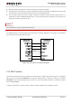
3.14. USB Interface
UC15 contains one integrated Universal Serial Bus (USB) transceiver which complies with the USB 2.0
specification and supports high speed (480Mbps), full speed (12Mbps) and low speed (1.5Mbps) mode.
The USB interface is primarily used for AT command, data transmission, software debug and firmware
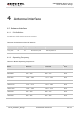
upgrade. The following table shows the pin definition of USB interface.
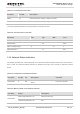
Table 20: USB Pin Description
More details about the USB 2.0 specifications, please visit http://www.usb.org/home.
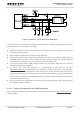
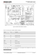
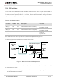
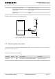
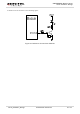
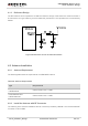
The following figure shows the reference circuit of USB interface.
Figure 34: Reference Circuit of USB Application
In order to ensure the USB interface design corresponding with the USB 2.0 specification, please comply
with the following principles.
It is important to route the USB signal traces as differential pairs with total grounding. The impedance
of USB differential trace is 90ohm.
Pin Name Pin No.
I/O Description Comment
USB_DP 62 IO USB differential data bus (positive).
Require differential
impedance of 90Ω.
USB_DM 63 IO USB differential data bus (negative).
Require differential
impedance of 90Ω.
USB_VBUS 64 PI USB detection.
3.0~5.25V.
Typical 5.0V.