
User's Manual

UMTS/HSDPA Module Series
UC15 Hardware Design
UC15_Hardware_Design Confidential / Released 49 / 78
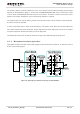
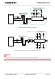
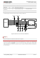
The following figure shows the reference design of the 8-pin USIM card.
Module
USIM_VDD
USIM_GND
USIM_RST
USIM_CLK
USIM_DATA
USIM_PRESENCE
22R
22R
22R
VDD_EXT
51K
100nF USIM holder
GND
GND
ESDA6V8AV6
33pF 33pF 33pF
VCC
RST
CLK
IO
VPP
GND
GND
USIM_VDD
15K
Figure 30: Reference Circuit of the 8-Pin USIM Card
Some AT commands are invalid when USIM card is not applied.
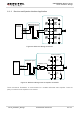
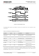
UC15 supports USIM card hot-plugging via the USIM_PRESENCE pin. For details, refer to document [1]
about the command AT+QSIMDET. If you do not need the USIM card detection function, keep
USIM_PRESENCE unconnected. The reference circuit for using a 6-pin USIM card holder is illustrated as
the following figure.
USIM_CLK 14 DO Clock signal of USIM card.
USIM_RST 15 DO Reset signal of USIM card.
USIM_
PRESENCE
11 DI USIM card detection input. 2.6V power domain
USIM_GND 8 Specified ground for USIM card.
NOTE