
User's Manual


UMTS/HSDPA Module Series
UC15 Hardware Design
UC15_Hardware_Design Confidential / Released 39 / 78
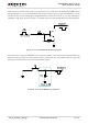
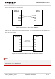
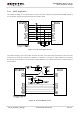
The following figure is an example of connection between module and PC. A RS232 level shifter IC or
circuit must be inserted between module and PC, since UART interface do not support the RS232 level,
while support the CMOS level only.
Figure 19: RS232 Level Shift Circuit
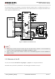
1. Rising edge on DTR will let the module exit from the data mode by default. It can be disabled by
command. Refer to document [1] about AT&D and AT&V for details.
2. DCD is used as data mode indication. Please refer to document [1] about command AT&C and
AT&V for details.
3.10. Behavior of the RI
You can use command AT+QCFG=“risignaltype”, “physical” to configure RI behavior:
No matter which port URC is presented on, URC will trigger the behavior on RI pin.
NOTES