
User's Manual


UMTS/HSDPA Module Series
UC15 Hardware Design
UC15_Hardware_Design Confidential / Released 38 / 78
3.9.2. UART Application
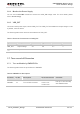
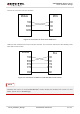
The reference design of 3.3V level match is shown as below. When the peripheral MCU/ARM system is
3V, the divider resistor should be changed from 3.6K to 6.8K.
Figure 17: 3.3V Level Match Circuit
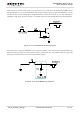
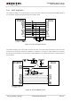
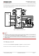
The reference design of 5V level match is shown as below. The construction of dotted line can refer to the
construction of solid line. Please pay attention to direction of connection. Input dotted line of module
should refer to input solid line of the module. Output dotted line of module should refer to output solid line
of the module.
Figure 18: 5V Level Match Circuit