
User's Manual

UMTS/HSDPA Module Series
UC15 Hardware Design
UC15_Hardware_Design Confidential / Released 24 / 78
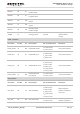
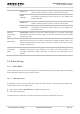
3.4. Operating Modes
The table below briefly summarizes the various operating modes.
Table 5: Overview of Operating Modes
2.6V only.
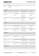
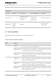
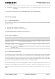
Other Pins
Pin Name Pin No. I/O Description DC Characteristics Comment
AP_READY 2 DI
Application process
or sleep state
detection.
V
IL
min=-0.3V
V
IL
max=0.91V
V
IH
min=1.69V
V
IH
max=2.9V
2.6V power domain.
RESERVED
1,3~5,9~
10,16,27
~33,66,
69~80
Reserved.
Keep these pins
unconnected.
Mode Details
Normal Operation
GSM Idle
Software is active. The module has registered to the GSM network
and is ready to send and receive data.
GSM Talk/Data
GSM connection is ongoing. In this mode, the power consumption
is decided by the configuration of power control level (PCL),
dynamic DTX control and the working RF band.
GPRS Idle
The module is ready for GPRS data transfer, but no data transfer
is going on. In this case, power consumption depends on network
setting and GPRS configuration.
GPRS Data
There is GPRS data in transfer (PPP, TCP or UDP). In this mode,
power consumption is decided by the PCL, working RF band and
GPRS multi-slot configuration.
EDGE Idle
The module is ready for data transfer in EDGE mode, but no data
is currently sent or received. In this case, power consumption
depends on network settings and EDGE configuration.
EDGE Data
There is EDGE data in transfer (PPP, TCP or UDP). In this mode,
power consumption is decided by the PCL, working RF band and
EDGE multi-slot configuration.