
User's Manual

UMTS/HSDPA Module Series
UC15 Hardware Design
UC15_Hardware_Design Confidential / Released 18 / 78
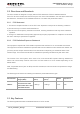
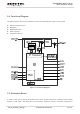
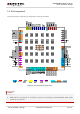
3.2. Pin Assignment
The following figure shows the pin assignment of the UC15 module.
Figure 2: Pin Assignment (Top View)
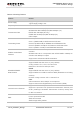
1. Keep all RESERVED pins and unused pins unconnected.
2. GND pads 81~108 should be connected to ground in the design, and RESERVED pads 69~80
should be unconnected.
NOTES