
User Manual


GSM/GPRS Module Series
GC10 Hardware Design
GC10_Hardware_Design Confidential / Released 55 / 76
4
Antenna Interface
The Pin 38 is the RF antenna pad. The RF interface has an impedance of 50Ω.
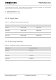
Table 16: Pin Definition of the RF_ANT
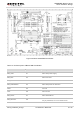
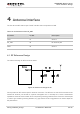
4.1. RF Reference Design
The reference design for RF is shown as below:
Figure 40: Reference Design for RF
GC10 provides an RF antenna pad for antenna connection. The RF trace in host PCB connected to the
module RF antenna pad should be coplanar waveguide line or microstrip line, whose characteristic
impedance should be close to 50Ω. GC10 comes with grounding pads which are next to the antenna pad
in order to give a better grounding. Besides, a ∏ type match circuit is suggested to be used to adjust the
RF performance.
Pin Name Pin NO. Description
GND 37 Ground
RF_ANT 38 RF antenna pad
GND 39 Ground