
User Manual


GSM/GPRS Module Series
GC10 Hardware Design
GC10_Hardware_Design Confidential / Released 47 / 76
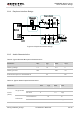
3.9. SIM Card Interface
3.9.1. SIM Card Application
The SIM interface supports the functionality of the GSM Phase 1 specification and also supports the
functionality of the new GSM Phase 2+ specification for FAST 64 kbps SIM card, which is intended to use
with a SIM application Tool-kit.
The SIM interface is powered by an internal regulator in the module. Both 1.8V and 3.0V SIM Cards are
supported.
Table 11: Pin Definition of the SIM Interface
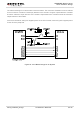
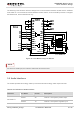
Figure 32 is the reference circuit for SIM interface, and here an 8-pin SIM card holder is used.
The pin SIM_PRESENCE is used to detect whether the tray of the Molex SIM socket, which is used for
holding SIM card, is presented in the card socket. When the tray is inserted in the socket,
SIM_PRESENCE is in low level. Regardless of the SIM card is in the tray or not, the change of
SIM_PRESENCE level from high to low prompts the module to initialize SIM card. In default configuration,
SIM card detection function is disabled. Customer’s application can use “AT+QSIMDET=1,0” and
“AT+QSIMDET=0,0” to switch on and off the SIM card detection function. For details of this AT command,
AOUT2
(SPK2)
Single-ended
Load resistance 32 Ω
Reference level 0 1.0 Vpp
Maximum Driving Current
Limit of SPK1 and SPK2
SPK1 80 mA
SPK2 25 mA
Pin Name Pin NO. Description
23 SIM_VDD Supply power for SIM card. Automatic detection of SIM card voltage.
24 SIM_RST SIM card reset.
25 SIM_DATA SIM card data I/O.
26 SIM_CLK SIM card clock.
27 SIM_GND SIM card ground.
28 SIM_PRESENCE SIM card detection