
User Manual


GSM/GPRS Module Series
GC10 Hardware Design
GC10_Hardware_Design Confidential / Released 42 / 76
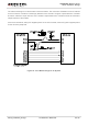
AIN1 and AIN2 can be used for input of microphone. An electret microphone is usually used. AIN1 and
AIN2 are both differential input channels.
AOUT1 is used for output of the receiver. This channel is typically used for a receiver built into a handset.
AOUT1 channel is a differential channel. If it is used as a speaker, an amplifier should be employed.
AOUT2 is used for output of earphone, which can be used as a single-ended channel. SPK2P and AGND
can establish a pseudo differential mode.
All of these two audio channels support voice and ringtone output, and so on, and can be switched by
“AT+QAUDCH” command. For more details, please refer to the document [1].
Use AT command “AT+QAUDCH” to select audio channel:
0--AIN1/AOUT1 (main audio channel), the default value is 0.
1--AIN2/AOUT2 (auxiliary audio channel), this channel is used for earphone.
For each channel, you can use AT+QMIC to adjust the input gain level of microphone. You can also use
“AT+CLVL” to adjust the output gain level of receiver. “AT+QSIDET” is used to set the side-tone gain level.
For more details, please refer to the document [1].
3.8.1. Decrease TDD Noise and Other Noises
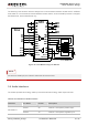
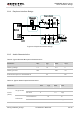
The 47pF capacitor is applied for filtering out 900MHz RF interference when the module is transmitting at
GSM900MHz. Without placing this capacitor, TDD noise could be heard. Moreover, the 10pF capacitor
here is for filtering out 1800MHz RF interference. However, the resonant frequency point of a capacitor
largely depends on the material and production technique. Therefore, you would have to discuss with its
capacitor vendor to choose the most suitable capacitor for filtering out GSM850MHz, GSM900MHz,
DCS1800MHz and PCS1900MHz separately.
The severity degree of the RF interference in the voice channel during GSM transmitting period largely
depends on the application design. In some cases, GSM900 TDD noise is more severe; while in other
SPK1P 22 Channel 1 audio positive output
SPK1N 21 Channel 1 audio negative output
AIN2/AOUT2
MIC2P 18 Channel 2 microphone positive input
MIC2N 17 Channel 2 microphone negative input
SPK2P 16 Channel 2 audio single-ended output
AGND 15 Form a pseudo-differential pair with SPK2P