
User Manual


GSM/GPRS Module Series
GC10 Hardware Design
GC10_Hardware_Design Confidential / Released 41 / 76
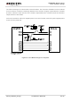
The following circuit shows a reference design for the communication between module and PC. A RS232
level shifter IC or circuit must be inserted between module and PC, since the UART port does not support
the RS232 level, but the CMOS level only.
Figure 25: Level Match Design for RS-232
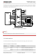
For three-line UART port, the UART to USB mode can also be used.
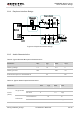
3.8. Audio Interfaces
The module provides two analogy audio input channels and two analogy audio output channels.
Table 8: Pin Definition of Audio Interface
Interfaces Pin Name Pin NO. Description
AIN1/AOUT1
MIC1P 20 Channel 1 microphone positive input
MIC1N 19 Channel 1 microphone negative input
NOTE