
User Manual


GSM/GPRS Module Series
GC10 Hardware Design
GC10_Hardware_Design Confidential / Released 40 / 76
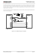
The reference design for 5V level match is shown as below. The connection of dotted line can be referred
to the connection of solid line. Please pay attention to the direction of signal. Input dotted line of module
should be referred to input solid line of the module. Output dotted line of module should be referred to
output solid line of the module.
As to the circuit below, VDD_EXT supplies power for the I/O of module, while VCC_MCU supplies power
for the I/O of the peripheral.
Figure 24: Level Match Design for 5V System