
User Manual


GSM/GPRS Module Series
GC10 Hardware Design
GC10_Hardware_Design Confidential / Released 39 / 76
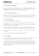
Figure 22: The Connection of Firmware Debugging and Upgrade
Because the debug port uses a high baud rate 921600bps configuration, when connecting a PC for
debugging and upgrading, the UART to USB mode is recommended. The test points for debug UART is
recommended to be reserved, for detailed design, please refer to the document [12].
3.7.3. UART Application
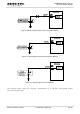
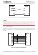
VDD_EXT is the reference voltage level for UART of GC10, the 1K resistors is recommended to be added
on the UART lines, the reference circuit is shown as below. This circuit is also applicable in 2.8V or 3.0V
systems.
Figure 23: Level Match Design for 3.3V System
NOTE