
User Manual


GSM/GPRS Module Series
GC10 Hardware Design
GC10_Hardware_Design Confidential / Released 34 / 76
Figure 18: Charging Characteristics of Seiko’s XH414H-IV01E
3.7. Serial Interfaces
The module provides two universal asynchronous serial ports: UART port and debug port. The module is
designed as a DCE (Data Communication Equipment), following the traditional DCE-DTE (Data Terminal
Equipment) connection. Autobauding function supports baud rate from 4800bps to 115200bps.
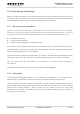
The UART port:
TXD: Send data to RXD of DTE.
RXD: Receive data from TXD of DTE.
RTS: Request to send.
CTS: Clear to send.
DTR: DTE is ready and inform DCE (this pin can wake the module up).
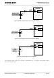
RI: Ring indicator (when the call, SMS, data of the module are coming, the module will output signal
to inform DTE).
DCD: Data carrier detection (the validity of this pin demonstrates the communication link is set up).
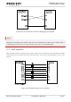
The module disables hardware flow control by default. When hardware flow control is required, RTS and
CTS should be connected to the host. AT command “AT+IFC=2,2” is used to enable hardware flow
control. AT command “AT+IFC=0,0” is used to disable the hardware flow control. For more details, please
refer to the document [1].
NOTE