
User Manual


GSM/GPRS Module Series
GC10 Hardware Design
GC10_Hardware_Design Confidential / Released 27 / 76
After power down, no further AT commands can be executed, only the RTC is still active. The power
down mode can be indicated by the VDD_EXT pin (the NETLIGHT pin can also be used.), which is a low
level voltage in this mode.
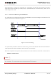
3.4.2.1. Power Down Module by the PWRKEY Pin
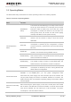
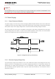
It is a safe way to turn off the module by driving the PWRKEY to a low level voltage for a certain time. The
power down scenario is illustrated in Figure 10:
Figure 10: Turn-off Timing
The power down procedure causes the module to log off from the network and allows the firmware to
save important data before completely disconnecting the power supply.
Before the completion of the power down procedure, the module sends the result code, shown as below:
NORMAL POWER DOWN
When autobauding is active and DTE&DCE are not correctly synchronized after start-up, this result code
will not appear. It is recommended to set a fixed baud rate for the module.
NOTE