
User Manual


GSM/GPRS Module Series
GC10 Hardware Design
GC10_Hardware_Design Confidential / Released 24 / 76
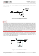
Figure 5: Reference Circuit for Power Supply
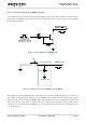
If a switching power converter is used, please follow the diagram to design the circuit, it is beneficial to
maintain stable power supply for the module.
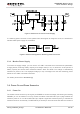
Figure 6: Reference Diagram for Switching Power Converter
3.3.4. Monitor Power Supply
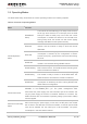
To monitor the supply voltage, you can use the “AT+CBC” command which includes three parameters:
charging status, remaining battery capacity and voltage value (in mV). It returns the 0-100 percent of
battery capacity and actual value measured between VBAT and GND. The voltage is automatically
measured in period of 5s. The displayed voltage (in mV) is averaged over the last measuring period
before the “AT+CBC” command is executed.
For details, please refer to document [1].
3.4. Power On and Down Scenarios
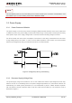
3.4.1. Power On
The module can be turned on by driving the pin PWRKEY to a low level voltage, after booting successfully,
PWRKEY pin can be released. You may monitor the status of the NETLIGHT pin to judge whether the
module is power-on or not. When NETLIGHT pin outputs a signal with certain frequency, it indicates the
module is turned on successfully. The NETLIGHT pin will keep in low level all the time after the module is