
User's Manual

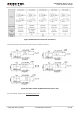
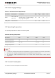


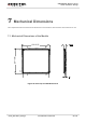
Table Of Contents
- About the Document
- Contents
- Table Index
- Figure Index
- 1 Introduction
- 2 Product Concept
- 3 Application Interface
- 3.1. General Description
- 3.2. Pin Assignment
- 3.3. Pin Description
- 3.4. Operating Modes
- 3.5. Power Saving
- 3.6. Power Supply
- 3.7. Turn on and off Scenarios
- 3.8. Reset the Module
- 3.9. RTC Backup
- 3.10. UART Interface
- 3.11. USIM Card Interface
- 3.12. USB Interface
- 3.13. PCM and I2C Interface
- 3.14. ADC Function
- 3.15. Network Status Indication
- 3.16. Operating Status Indication
- 3.17. Behavior of the RI
- 4 GNSS Receiver
- 5 Antenna Interface
- 6 Electrical, Reliability and Radio Characteristics
- 7 Mechanical Dimensions
- 8 Storage and Manufacturing
- 9 Appendix A Reference
UMTS/HSPA Module Series
UC20 Hardware Design
UC20_Hardware_Design Confidential / Released 65 / 84
6.2. Power Supply Ratings
Table 31: The Module Power Supply Ratings
Parameter
Description
Conditions
Min.
Typ.
Max.
Unit
VBAT
VBAT_BB and
VBAT_RF
Voltage must stay within the
min/max values, including voltage
drop, ripple and spikes.
3.4
3.8
4.3
V
USB_VBUS
USB detection
3.0
5.0
5.25
V
6.3. Operating Temperature
The operating temperature is listed in the following table.
Table 32: Operating Temperature
Parameter
Min
Typ.
Max
Unit
Normal Temperature
-35
25
75
ºC
Restricted Operation
1)
-40~ -35
75 ~ 85
ºC
Storage Temperature
-45
90
ºC
1. “
1)
” When the module works within the temperature range, the deviations from the RF specification
may occur. For example, the frequency error or the phase error would increase.
2. The maximum surface temperature may be up to 100ºC when module works at 85ºC ambient
temperature.
6.4. Current Consumption
The values of current consumption are shown below.
NOTE