
User's Manual
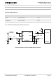
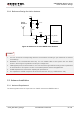

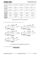


Table Of Contents
- About the Document
- Contents
- Table Index
- Figure Index
- 1 Introduction
- 2 Product Concept
- 3 Application Interface
- 3.1. General Description
- 3.2. Pin Assignment
- 3.3. Pin Description
- 3.4. Operating Modes
- 3.5. Power Saving
- 3.6. Power Supply
- 3.7. Turn on and off Scenarios
- 3.8. Reset the Module
- 3.9. RTC Backup
- 3.10. UART Interface
- 3.11. USIM Card Interface
- 3.12. USB Interface
- 3.13. PCM and I2C Interface
- 3.14. ADC Function
- 3.15. Network Status Indication
- 3.16. Operating Status Indication
- 3.17. Behavior of the RI
- 4 GNSS Receiver
- 5 Antenna Interface
- 6 Electrical, Reliability and Radio Characteristics
- 7 Mechanical Dimensions
- 8 Storage and Manufacturing
- 9 Appendix A Reference
UMTS/HSPA Module Series
UC20 Hardware Design
UC20_Hardware_Design Confidential / Released 62 / 84
Table 29: Antenna Requirements
Type
Requirements
GNSS
Frequency range: 1565~1607 MHz
Polarization: RHCP or linear
VSWR: < 2 (Typ.)
Passive antenna gain: > 0dBi
Active antenna noise figure: < 1.5dB
Active antenna gain: > -2dBi
Active antenna embedded LNA gain: 20dB (Typ.)
Active antenna total gain: > 18dBi (Typ.)
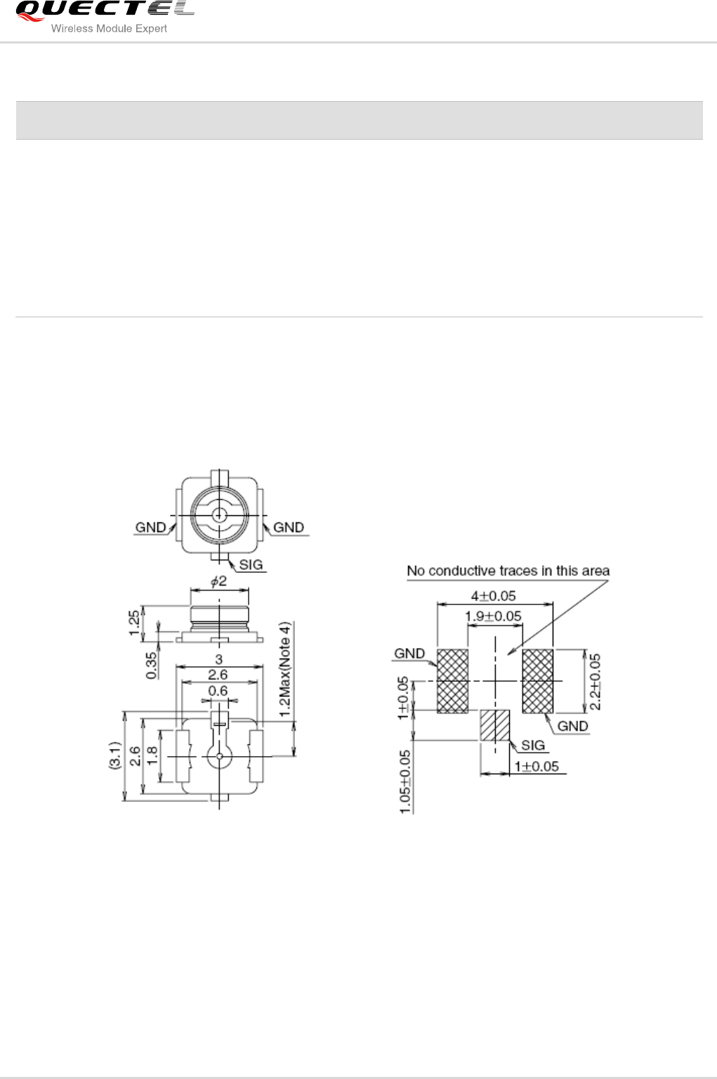
5.3.2. Install the Antenna with RF Connector
The following figure is the antenna installation with RF connector provided by HIROSE. The
recommended RF connector is UF.L-R-SMT.
Figure 37: Dimensions of the UF.L-R-SMT Connector (Unit: mm)
You can use U.FL-LP serial connector listed in the following figure to match the UF.L-R-SMT.