
User's Manual
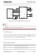
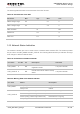
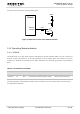
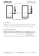

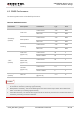

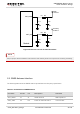
Table Of Contents
- About the Document
- Contents
- Table Index
- Figure Index
- 1 Introduction
- 2 Product Concept
- 3 Application Interface
- 3.1. General Description
- 3.2. Pin Assignment
- 3.3. Pin Description
- 3.4. Operating Modes
- 3.5. Power Saving
- 3.6. Power Supply
- 3.7. Turn on and off Scenarios
- 3.8. Reset the Module
- 3.9. RTC Backup
- 3.10. UART Interface
- 3.11. USIM Card Interface
- 3.12. USB Interface
- 3.13. PCM and I2C Interface
- 3.14. ADC Function
- 3.15. Network Status Indication
- 3.16. Operating Status Indication
- 3.17. Behavior of the RI
- 4 GNSS Receiver
- 5 Antenna Interface
- 6 Electrical, Reliability and Radio Characteristics
- 7 Mechanical Dimensions
- 8 Storage and Manufacturing
- 9 Appendix A Reference

UMTS/HSPA Module Series
UC20 Hardware Design
UC20_Hardware_Design Confidential / Released 58 / 84
5 Antenna Interface
UC20 antenna interface includes a main UMTS antenna, an optional UMTS Rx-diversity antenna, which
is used to improve UMTS’s receiving performance, and a GNSS antenna. The antenna interface has an
impedance of 50Ω.
5.1. UMTS Antenna Interface
5.1.1. Pin Definition
The main antenna and UMTS Rx-diversity antenna pins definition are shown below.
Table 25: Pin Definition of the RF Antenna
Pin Name
Pin No.
I/O
Description
Comment
ANT_MAIN
49
IO
Main antenna
50Ω impedance
ANT_DIV
35
AI
Diversity antenna
50Ω impedance
5.1.2. Operating Frequency
Table 26: The Module Operating Frequencies
Band
Receive
Transmit
Unit
UMTS 1900
1930 ~ 1990
1850 ~ 1910
MHz
UMTS 850
869 ~ 894
824 ~ 849
MHz
5.1.3. Reference Design
The reference design of main antenna and UMTS Rx-diversity antenna is shown as below. It should
reserve a π-type matching circuit for better RF performance. The capacitors are not mounted by default.