
User's Manual
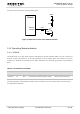


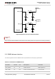
Table Of Contents
- About the Document
- Contents
- Table Index
- Figure Index
- 1 Introduction
- 2 Product Concept
- 3 Application Interface
- 3.1. General Description
- 3.2. Pin Assignment
- 3.3. Pin Description
- 3.4. Operating Modes
- 3.5. Power Saving
- 3.6. Power Supply
- 3.7. Turn on and off Scenarios
- 3.8. Reset the Module
- 3.9. RTC Backup
- 3.10. UART Interface
- 3.11. USIM Card Interface
- 3.12. USB Interface
- 3.13. PCM and I2C Interface
- 3.14. ADC Function
- 3.15. Network Status Indication
- 3.16. Operating Status Indication
- 3.17. Behavior of the RI
- 4 GNSS Receiver
- 5 Antenna Interface
- 6 Electrical, Reliability and Radio Characteristics
- 7 Mechanical Dimensions
- 8 Storage and Manufacturing
- 9 Appendix A Reference

UMTS/HSPA Module Series
UC20 Hardware Design
UC20_Hardware_Design Confidential / Released 57 / 84
4.3. Layout Guideline
The following layout guideline should be taken into account in your design.
Maximize the distance between the GNSS antenna and the main UMTS antenna.
Noisy digital circuits such as the USIM card, USB interface, Camera module, Display connector and
SD card should be away from the antenna.
Use ground vias around the GNSS trace and sensitive analog signal traces to provide coplanar
isolation and protection.
Keep 50 ohm characteristic impedance of the ANT_GNSS trace.
Refer to chapter 5 for GNSS reference design and antenna consideration.