
User's Manual
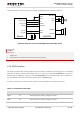
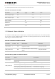
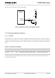

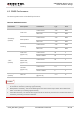

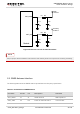
Table Of Contents
- About the Document
- Contents
- Table Index
- Figure Index
- 1 Introduction
- 2 Product Concept
- 3 Application Interface
- 3.1. General Description
- 3.2. Pin Assignment
- 3.3. Pin Description
- 3.4. Operating Modes
- 3.5. Power Saving
- 3.6. Power Supply
- 3.7. Turn on and off Scenarios
- 3.8. Reset the Module
- 3.9. RTC Backup
- 3.10. UART Interface
- 3.11. USIM Card Interface
- 3.12. USB Interface
- 3.13. PCM and I2C Interface
- 3.14. ADC Function
- 3.15. Network Status Indication
- 3.16. Operating Status Indication
- 3.17. Behavior of the RI
- 4 GNSS Receiver
- 5 Antenna Interface
- 6 Electrical, Reliability and Radio Characteristics
- 7 Mechanical Dimensions
- 8 Storage and Manufacturing
- 9 Appendix A Reference
UMTS/HSPA Module Series
UC20 Hardware Design
UC20_Hardware_Design Confidential / Released 52 / 84
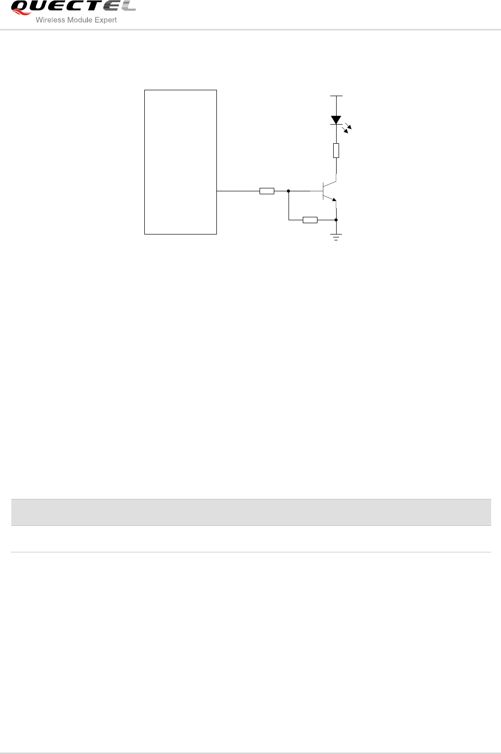
A reference circuit is shown in the following figure.
4.7K
47K
VBAT
2.2K
Module
Network
Indicator
Figure 31: Reference Circuit of the Network Indicator
3.16. Operating Status Indication
3.16.1. STATUS
The STATUS pin is an open drain output for indicating the module operation status. You can connect it to
a GPIO of DTE with pulled up, or as LED indication circuit as below. When the module is turned on
normally, the STATUS will present the low state. Otherwise, the STATUS will present high-impedance
state.
Table 21: Pin Definition of STATUS
Pin Name
Pin No.
I/O
Description
Comment
STATUS
61
OD
Indicate the module operation status.
Require external pull-up.
The following figure shows different design circuit of STATUS, you can choose either one according to
your application demands.