
User's Manual
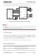
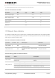

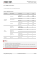

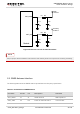
Table Of Contents
- About the Document
- Contents
- Table Index
- Figure Index
- 1 Introduction
- 2 Product Concept
- 3 Application Interface
- 3.1. General Description
- 3.2. Pin Assignment
- 3.3. Pin Description
- 3.4. Operating Modes
- 3.5. Power Saving
- 3.6. Power Supply
- 3.7. Turn on and off Scenarios
- 3.8. Reset the Module
- 3.9. RTC Backup
- 3.10. UART Interface
- 3.11. USIM Card Interface
- 3.12. USB Interface
- 3.13. PCM and I2C Interface
- 3.14. ADC Function
- 3.15. Network Status Indication
- 3.16. Operating Status Indication
- 3.17. Behavior of the RI
- 4 GNSS Receiver
- 5 Antenna Interface
- 6 Electrical, Reliability and Radio Characteristics
- 7 Mechanical Dimensions
- 8 Storage and Manufacturing
- 9 Appendix A Reference

UMTS/HSPA Module Series
UC20 Hardware Design
UC20_Hardware_Design Confidential / Released 51 / 84
The following table describes the characteristic of the ADC function.
Table 18: Characteristic of the ADC
Parameter
Min.
Typ.
Max.
Unit
ADC0 voltage range
0.2
2.1
V
ADC1 voltage range
0.2
4.2
V
ADC resolution
15
bits
Offset error
3.5
%
Gain error
2.5
%
3.15. Network Status Indication
The network indication pins can be used to drive a network status indicator LED. The module provides
two pins which are NET_MODE and NET_STATUS. The following tables describe pin definition and logic
level changes in different network status.
Table 19: Pin Definition of Network Indicator
Pin Name
Pin No.
I/O
Description
Comment
NET_MODE
5
DO
Indicate the module network
registration mode.
1.8V power domain.
NET_STATUS
6
DO
Indicate the module network activity
status.
1.8V power domain.
Table 20: Working State of the Network Indicator
Pin name
Status
Description
NET_MODE
Always High.
Registered in 3G network.
Always Low.
Others.
NET_STATUS
Flicker slowly (200ms High/1800ms Low).
Networks searching.
Flicker slowly (1800ms High/200ms Low).
Idle.
Flicker quickly (125ms High/125ms Low).
Data transfer is ongoing.
Always High.
Voice calling.