
User's Manual
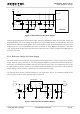
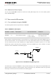

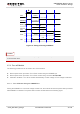

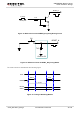
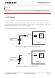
Table Of Contents
- About the Document
- Contents
- Table Index
- Figure Index
- 1 Introduction
- 2 Product Concept
- 3 Application Interface
- 3.1. General Description
- 3.2. Pin Assignment
- 3.3. Pin Description
- 3.4. Operating Modes
- 3.5. Power Saving
- 3.6. Power Supply
- 3.7. Turn on and off Scenarios
- 3.8. Reset the Module
- 3.9. RTC Backup
- 3.10. UART Interface
- 3.11. USIM Card Interface
- 3.12. USB Interface
- 3.13. PCM and I2C Interface
- 3.14. ADC Function
- 3.15. Network Status Indication
- 3.16. Operating Status Indication
- 3.17. Behavior of the RI
- 4 GNSS Receiver
- 5 Antenna Interface
- 6 Electrical, Reliability and Radio Characteristics
- 7 Mechanical Dimensions
- 8 Storage and Manufacturing
- 9 Appendix A Reference
UMTS/HSPA Module Series
UC20 Hardware Design
UC20_Hardware_Design Confidential / Released 37 / 84
Use the RESET_N only when turning off the module by the command AT+QPOWD and the PWRKEY pin
failed.
3.9. RTC Backup
The RTC (Real Time Clock) can be powered by an external power source through the pin VRTC when the
module is powered down and there is no power supply for the VBAT. It is also available to charge the
battery on the VRTC when module is turned on. You can choose rechargeable battery, capacitor or
non-rechargeable battery depending on different applications.
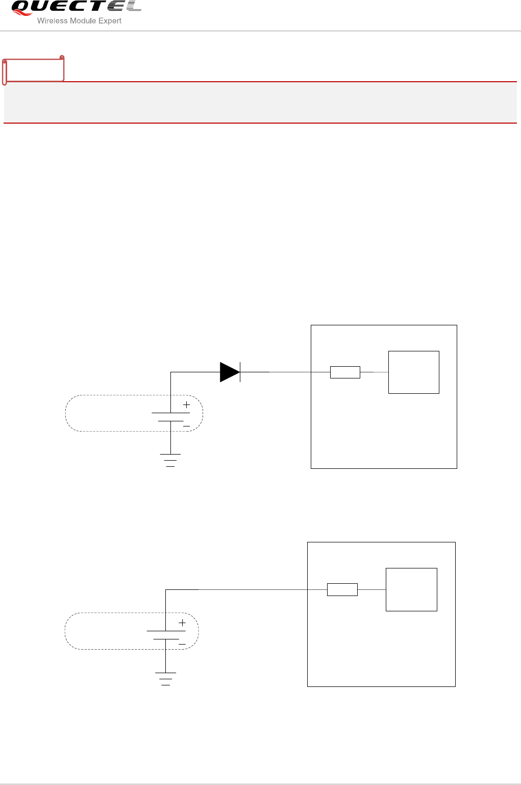
The following figures show the various sample circuits for VRTC backup.
Module
RTC
Core
R
VRTC
Non-chargeable
Battery
Figure 15: RTC Supply from Non-chargeable Battery
Rechargeable
Battery
Module
RTC
Core
R
VRTC
Figure 16: RTC Supply from Rechargeable Battery
NOTE