
User's Manual
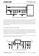
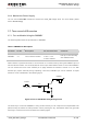

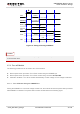

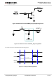
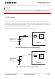
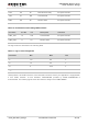
Table Of Contents
- About the Document
- Contents
- Table Index
- Figure Index
- 1 Introduction
- 2 Product Concept
- 3 Application Interface
- 3.1. General Description
- 3.2. Pin Assignment
- 3.3. Pin Description
- 3.4. Operating Modes
- 3.5. Power Saving
- 3.6. Power Supply
- 3.7. Turn on and off Scenarios
- 3.8. Reset the Module
- 3.9. RTC Backup
- 3.10. UART Interface
- 3.11. USIM Card Interface
- 3.12. USB Interface
- 3.13. PCM and I2C Interface
- 3.14. ADC Function
- 3.15. Network Status Indication
- 3.16. Operating Status Indication
- 3.17. Behavior of the RI
- 4 GNSS Receiver
- 5 Antenna Interface
- 6 Electrical, Reliability and Radio Characteristics
- 7 Mechanical Dimensions
- 8 Storage and Manufacturing
- 9 Appendix A Reference
UMTS/HSPA Module Series
UC20 Hardware Design
UC20_Hardware_Design Confidential / Released 35 / 84
The uncritical voltage is 3.4V to 4.3V, If the voltage > 4.3V or < 3.4V the module would automatically shut
down itself.
If the voltage < 3.4V, the following URC will be presented:
+QIND: “vbatt”,-2
If the voltage > 4.3V, the following URC will be presented:
+QIND: “vbatt”,2
The value of voltage threshold can be revised by command AT+QCFG=“vbatt”, refer to document [1]
for details.
3.8. Reset the Module
The RESET_N can be used to reset the module.
Table 8: RESET_N Pin Description
Pin Name
Pin No.
Description
DC Characteristics
Comment
RESET_N
20
Reset the module.
V
IH
max = 2.1V
V
IH
min = 1.3V
V
IL
max = 500mV
Pull-up to 1.8V internally
with 200kΩ resistor.
Active low.
You can reset the module by driving the RESET_N to a low level voltage for more than 150ms and then
releasing.
The recommended circuit is similar to the PWRKEY control circuit. You can use open drain/collector
driver or button to control the RESET_N.
NOTE