
User's Manual
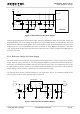
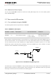

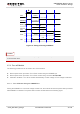

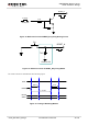
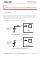
Table Of Contents
- About the Document
- Contents
- Table Index
- Figure Index
- 1 Introduction
- 2 Product Concept
- 3 Application Interface
- 3.1. General Description
- 3.2. Pin Assignment
- 3.3. Pin Description
- 3.4. Operating Modes
- 3.5. Power Saving
- 3.6. Power Supply
- 3.7. Turn on and off Scenarios
- 3.8. Reset the Module
- 3.9. RTC Backup
- 3.10. UART Interface
- 3.11. USIM Card Interface
- 3.12. USB Interface
- 3.13. PCM and I2C Interface
- 3.14. ADC Function
- 3.15. Network Status Indication
- 3.16. Operating Status Indication
- 3.17. Behavior of the RI
- 4 GNSS Receiver
- 5 Antenna Interface
- 6 Electrical, Reliability and Radio Characteristics
- 7 Mechanical Dimensions
- 8 Storage and Manufacturing
- 9 Appendix A Reference
UMTS/HSPA Module Series
UC20 Hardware Design
UC20_Hardware_Design Confidential / Released 33 / 84
V
IL
≤ 0.5V
V
IH
≥ 1.3V
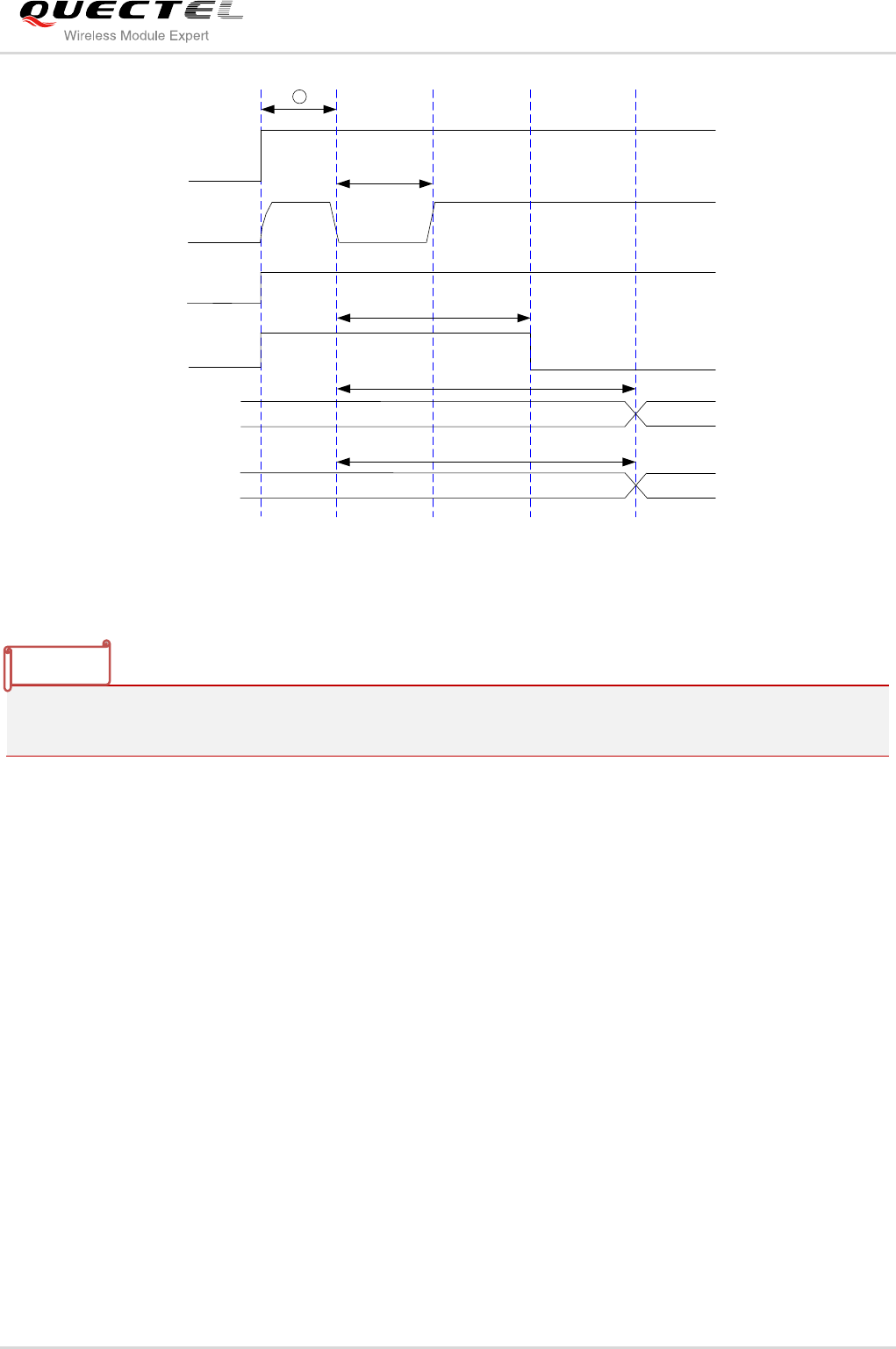
VBAT
PWRKEY
≥ 100ms
1
RESET_N
STATUS
(OD)
1.3 ~ 1.9s
Inactive
UART
Active
≥ 5s
Inactive
Active
USB
≥ 5s
Figure 10: Timing of Turning on Module
Make sure that VBAT is stable before pulling down PWRKEY pin. The time between them is
recommended 30ms.
3.7.2. Turn off Module
The following procedures can be used to turn off the module:
Normal power down procedure: Turn off the module using the PWRKEY pin.
Normal power down procedure: Turn off the module using command AT+QPOWD.
Automatic shutdown: Turn off the module automatically if under-voltage or over-voltage is detected.
3.7.2.1. Turn off Module Using the PWRKEY Pin
Driving the PWRKEY to a low level voltage at least 0.6s, the module will execute power-down procedure
after PWRKEY is released. The power-down scenario is illustrated as the following figure.
NOTES