
User's Manual
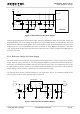
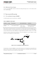

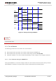

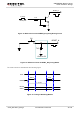
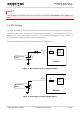
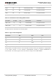
Table Of Contents
- About the Document
- Contents
- Table Index
- Figure Index
- 1 Introduction
- 2 Product Concept
- 3 Application Interface
- 3.1. General Description
- 3.2. Pin Assignment
- 3.3. Pin Description
- 3.4. Operating Modes
- 3.5. Power Saving
- 3.6. Power Supply
- 3.7. Turn on and off Scenarios
- 3.8. Reset the Module
- 3.9. RTC Backup
- 3.10. UART Interface
- 3.11. USIM Card Interface
- 3.12. USB Interface
- 3.13. PCM and I2C Interface
- 3.14. ADC Function
- 3.15. Network Status Indication
- 3.16. Operating Status Indication
- 3.17. Behavior of the RI
- 4 GNSS Receiver
- 5 Antenna Interface
- 6 Electrical, Reliability and Radio Characteristics
- 7 Mechanical Dimensions
- 8 Storage and Manufacturing
- 9 Appendix A Reference
UMTS/HSPA Module Series
UC20 Hardware Design
UC20_Hardware_Design Confidential / Released 31 / 84
3.6.4. Monitor the Power Supply
You can use the AT+CBC command to monitor the VBAT_BB voltage value. For more details, please
refer to document [1].
3.7. Turn on and off Scenarios
3.7.1. Turn on Module Using the PWRKEY
The following table shows the pin definition of PWRKEY.
Table 7: PWRKEY Pin Description
Pin Name
Pin No.
Description
DC Characteristics
Comment
PWRKEY
21
Turn on/off the module.
V
IH
max = 2.1V
V
IH
min = 1.3V
V
IL
max = 500mV
Pull-up to 1.8V internally
with 200kΩ resistor.
When UC20 is in power down mode, it can be turned on to normal mode by driving the PWRKEY pin to a
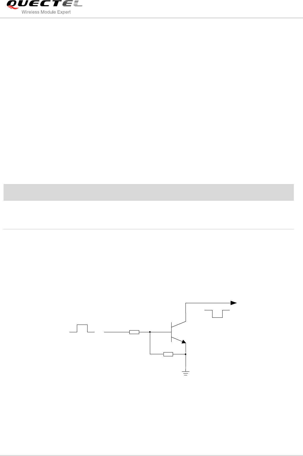
low level at least 100ms. It is recommended to use an open drain/collector driver to control the PWRKEY.
You can monitor the level of the STATUS pin to judge whether the module is turned on or not. After
STATUS pin (require external pull-up) outputting a low level, PWRKEY pin can be released. A simple
reference circuit is illustrated in the following figure.
Turn on pulse
PWRKEY
4.7K
47K
≥ 100ms
Figure 8: Turn on the Module Using Driving Circuit
The other way to control the PWRKEY is using a button directly. A TVS component is indispensable to be
placed nearby the button for ESD protection. When pressing the key, electrostatic strike may generate
from finger. A reference circuit is showed in the following figure.