
User's Manual
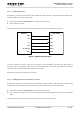
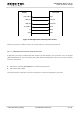
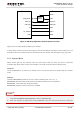
Table Of Contents
- About the Document
- Contents
- Table Index
- Figure Index
- 1 Introduction
- 2 Product Concept
- 3 Application Interface
- 3.1. General Description
- 3.2. Pin Assignment
- 3.3. Pin Description
- 3.4. Operating Modes
- 3.5. Power Saving
- 3.6. Power Supply
- 3.7. Turn on and off Scenarios
- 3.8. Reset the Module
- 3.9. RTC Backup
- 3.10. UART Interface
- 3.11. USIM Card Interface
- 3.12. USB Interface
- 3.13. PCM and I2C Interface
- 3.14. ADC Function
- 3.15. Network Status Indication
- 3.16. Operating Status Indication
- 3.17. Behavior of the RI
- 4 GNSS Receiver
- 5 Antenna Interface
- 6 Electrical, Reliability and Radio Characteristics
- 7 Mechanical Dimensions
- 8 Storage and Manufacturing
- 9 Appendix A Reference
UMTS/HSPA Module Series
UC20 Hardware Design
UC20_Hardware_Design Confidential / Released 27 / 84
USB_VBUS
USB_DP
USB_DM
AP_READY
VDD
USB_DP
USB_DM
GPIO
Module
Processor
GND
GND
RI
EINT
Figure 4: USB Application with Suspend Function
When the processor’s USB bus returns to resume state, the module will be woken up.
3.5.1.3. USB Application without Suspend Function
If application processor communicates with module via USB interface, and processor does not support
USB suspend function, you should disconnect USB_VBUS with additional control circuit to let the module
enter into sleep mode.
Execute AT command AT+QSCLK=1 to enable the sleep mode.
Disconnect USB_VBUS.
The following figure shows the connection between the module and application processor.