
User's Manual
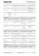
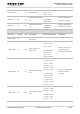
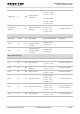
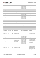
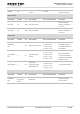
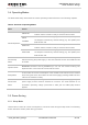
Table Of Contents
- About the Document
- Contents
- Table Index
- Figure Index
- 1 Introduction
- 2 Product Concept
- 3 Application Interface
- 3.1. General Description
- 3.2. Pin Assignment
- 3.3. Pin Description
- 3.4. Operating Modes
- 3.5. Power Saving
- 3.6. Power Supply
- 3.7. Turn on and off Scenarios
- 3.8. Reset the Module
- 3.9. RTC Backup
- 3.10. UART Interface
- 3.11. USIM Card Interface
- 3.12. USB Interface
- 3.13. PCM and I2C Interface
- 3.14. ADC Function
- 3.15. Network Status Indication
- 3.16. Operating Status Indication
- 3.17. Behavior of the RI
- 4 GNSS Receiver
- 5 Antenna Interface
- 6 Electrical, Reliability and Radio Characteristics
- 7 Mechanical Dimensions
- 8 Storage and Manufacturing
- 9 Appendix A Reference
UMTS/HSPA Module Series
UC20 Hardware Design
UC20_Hardware_Design Confidential / Released 24 / 84
AGND
22
Reserved for analog
ground.
Ground.
If unused, connect
this pin to ground.
I2C Interface
Pin Name
Pin No.
I/O
Description
DC Characteristics
Comment
I2C_SCL
41
OD
I2C serial clock.
External pull-up
resistor is required.
1.8V only.
I2C_SDA
42
OD
I2C serial data.
External pull-up
resistor is required.
1.8V only.
Other Pins
Pin Name
Pin No.
I/O
Description
DC Characteristics
Comment
WAKEUP_
IN
1
DI
Sleep mode control.
V
IL
min = -0.3V
V
IL
max = 0.6V
V
IH
min = 1.2V
V
IH
max = 2.0V
1.8V power domain.
Pull-up by default.
Low level wakes up
the module.
W_DISABL
E#
4
DI
Airplane mode
control.
V
IL
min = -0.3V
V
IL
max = 0.6V
V
IH
min = 1.2V
V
IH
max = 2.0V
1.8V power domain.
Pull-up by default.
In low level voltage,
module can enter into
airplane mode.
AP_READY
2
DI
Application
processor sleep
state detection.
V
IL
min = -0.3V
V
IL
max = 0.6V
V
IH
min = 1.2V
V
IH
max = 2.0V
1.8V power domain.
RESERVED Pins
Pin Name
Pin No.
I/O
Description
DC Characteristics
Comment
RESERV
ED
23,28~33,3
7~40,43,55
,73~84
Reserved
Keep these pins
unconnected.