
User's Manual
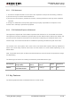
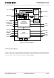
Table Of Contents
- About the Document
- Contents
- Table Index
- Figure Index
- 1 Introduction
- 2 Product Concept
- 3 Application Interface
- 3.1. General Description
- 3.2. Pin Assignment
- 3.3. Pin Description
- 3.4. Operating Modes
- 3.5. Power Saving
- 3.6. Power Supply
- 3.7. Turn on and off Scenarios
- 3.8. Reset the Module
- 3.9. RTC Backup
- 3.10. UART Interface
- 3.11. USIM Card Interface
- 3.12. USB Interface
- 3.13. PCM and I2C Interface
- 3.14. ADC Function
- 3.15. Network Status Indication
- 3.16. Operating Status Indication
- 3.17. Behavior of the RI
- 4 GNSS Receiver
- 5 Antenna Interface
- 6 Electrical, Reliability and Radio Characteristics
- 7 Mechanical Dimensions
- 8 Storage and Manufacturing
- 9 Appendix A Reference
UMTS/HSPA Module Series
UC20 Hardware Design
UC20_Hardware_Design Confidential / Released 16 / 84
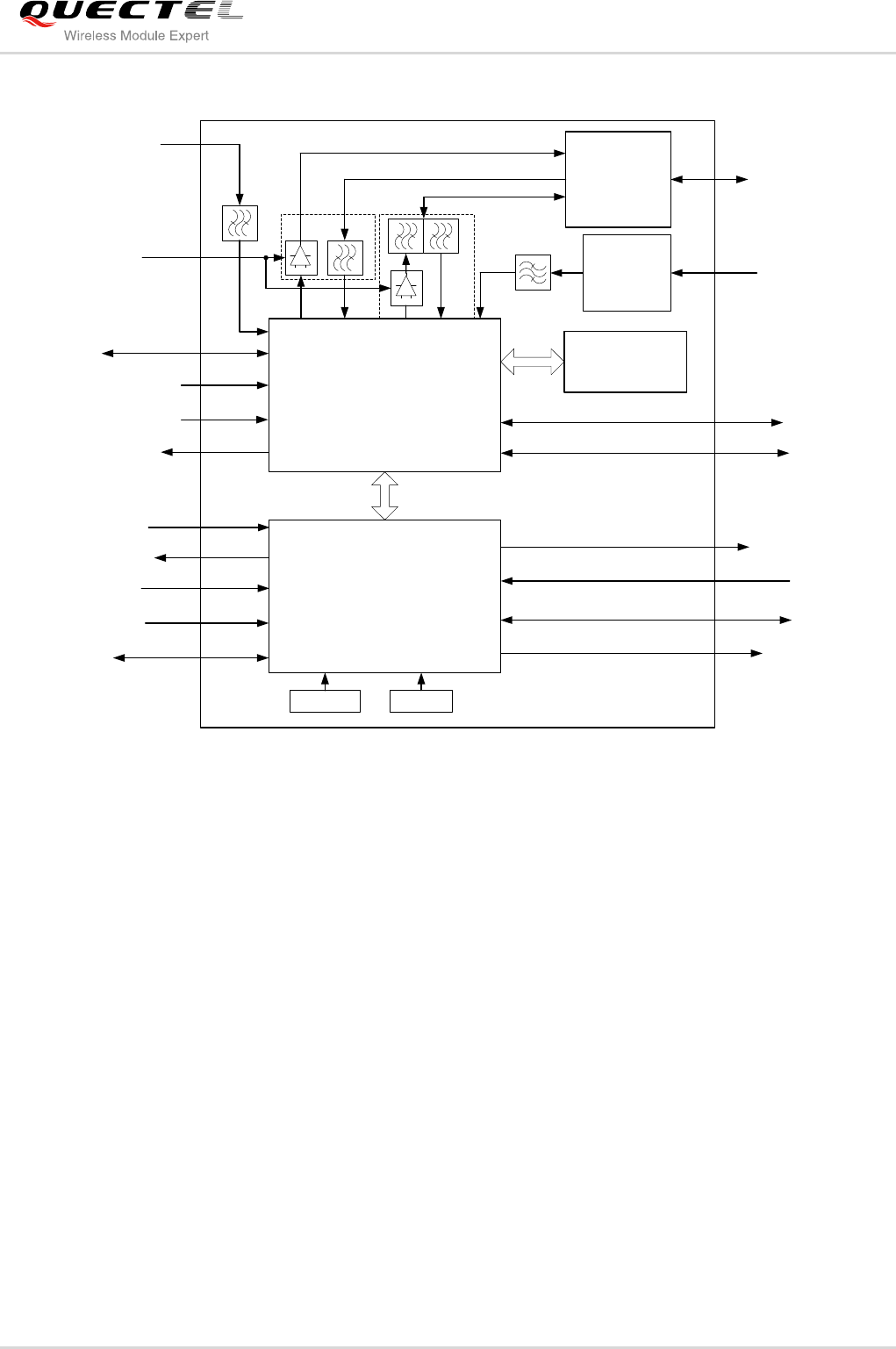
PWRKEY
RESET_N
32kHz
19.2MHz
Power
Management Unit
Baseband
RF Transceiver
GNSS Receiver
ANT_GNSS
RF
Switch
DDR RAM/
ANT_MAIN
USIM
STATUS
ADC
PCM
UART
VBAT_BB
USB
ANT_DIV
VBAT_RF
VDD_EXT
GSM
UMTS
RF
Switch
VDD_2V85
WAKEUP_IN
VRTC
SLEEP_IND
W_DISABLE#
NAND Flash
Figure 1: Functional Diagram
2.5. Evaluation Board
In order to help you to develop applications with UC20, Quectel supplies an evaluation board (EVB),
RS-232 to USB cable, USB data cable, power adapter, earphone, antenna and other peripherals to
control or test the module. For details, please refer to document [2].