
User's Manual


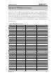

Table Of Contents
- Contents
- Table Index
- Figure Index
- 0. Revision history
- 1. Introduction
- 2. Product concept
- 3. Application interface
- 3.1. Pin
- 3.2. Operating modes
- 3.3. Power supply
- 3.4. Power on and down scenarios
- 3.5. Power saving
- 3.6. Summary of state transitions
- 3.7. RTC backup
- 3.8. Serial interfaces
- 3.9. Audio interfaces
- 3.10. SIM card interface
- 3.12. Behaviors of the RI
- 3.13. Network status indication
- 3.14. Operating status indication
- 4. Antenna interface
- 5. Electrical, reliability and radio characteristics
- 6. Mechanical dimensions
- 7. Storage and Manufacturing
- Appendix A: GPRS coding schemes
- Appendix B: GPRS multi-slot classes

M95 Hardware Design
M95_HD_V1.0 - 74 -
Appendix B: GPRS multi-slot classes
Twenty-nine classes of GPRS multi-slot modes are defined for MS in GPRS specification.
Multi-slot classes are product dependant, and determine the maximum achievable data rates in
both the uplink and downlink directions. Written as 3+1 or 2+2, the first number indicates the
amount of downlink timeslots, while the second number indicates the amount of uplink timeslots.
The active slots determine the total number of slots the GPRS device can use simultaneously for
both uplink and downlink communications. The description of different multi-slot classes is
shown in Table 30.
Table 30: GPRS multi-slot classes
Multislot class
Downlink slots
Uplink slots
Active slots
1
1
1
2
2
2
1
3
3
2
2
3
4
3
1
4
5
2
2
4
6
3
2
4
7
3
3
4
8
4
1
5
9
3
2
5
10
4
2
5
11
4
3
5
12
4
4
5
13
3
3
NA
14
4
4
NA
15
5
5
NA
16
6
6
NA
17
7
7
NA
18
8
8
NA
19
6
2
NA
20
6
3
NA
21
6
4
NA
22
6
4
NA
23
6
6
NA
24
8
2
NA
25
8
3
NA
26
8
4
NA
27
8
4
NA
28
8
6
NA
29
8
8
NA