
User's Manual
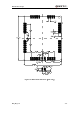

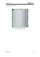

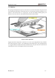
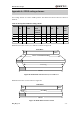
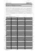

Table Of Contents
- Contents
- Table Index
- Figure Index
- 0. Revision history
- 1. Introduction
- 2. Product concept
- 3. Application interface
- 3.1. Pin
- 3.2. Operating modes
- 3.3. Power supply
- 3.4. Power on and down scenarios
- 3.5. Power saving
- 3.6. Summary of state transitions
- 3.7. RTC backup
- 3.8. Serial interfaces
- 3.9. Audio interfaces
- 3.10. SIM card interface
- 3.12. Behaviors of the RI
- 3.13. Network status indication
- 3.14. Operating status indication
- 4. Antenna interface
- 5. Electrical, reliability and radio characteristics
- 6. Mechanical dimensions
- 7. Storage and Manufacturing
- Appendix A: GPRS coding schemes
- Appendix B: GPRS multi-slot classes

M95 Hardware Design
M95_HD_V1.0 - 72 -
Time(s)
50
100
150 200 250 300
50
100
150
200
250
160℃
200℃
217
0
70s~120s
40s~60s
Between 1~3℃/S
Preheat Heating Cooling
℃
s
Liquids Temperature
Figure 46: Ramp-Soak-Spike reflow profile
7.3. Packaging
M95 modules are distributed in trays of 25 pieces each. This is especially suitable for the M95
according to SMT processes requirements.
The trays are stored inside a vacuum-sealed bag which is ESD protected. It should not be opened
until the devices are ready to be soldered onto the application.
Figure 47: Module tray