
User's Manual
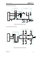
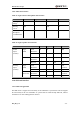
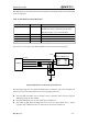
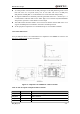
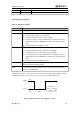
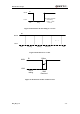
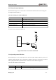
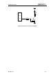
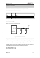
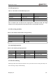
Table Of Contents
- Contents
- Table Index
- Figure Index
- 0. Revision history
- 1. Introduction
- 2. Product concept
- 3. Application interface
- 3.1. Pin
- 3.2. Operating modes
- 3.3. Power supply
- 3.4. Power on and down scenarios
- 3.5. Power saving
- 3.6. Summary of state transitions
- 3.7. RTC backup
- 3.8. Serial interfaces
- 3.9. Audio interfaces
- 3.10. SIM card interface
- 3.12. Behaviors of the RI
- 3.13. Network status indication
- 3.14. Operating status indication
- 4. Antenna interface
- 5. Electrical, reliability and radio characteristics
- 6. Mechanical dimensions
- 7. Storage and Manufacturing
- Appendix A: GPRS coding schemes
- Appendix B: GPRS multi-slot classes

M95 Hardware Design
M95_HD_V1.0 - 54 -
To avoid possible cross-talk from the SIM_CLK signal to the SIM_DATA signal be careful
that both traces are not placed closely next to each other. The traces of SIM_CLK,
SIM_DATA and SIM_RST are recommended to be around with GND independently.
All signals of SIM interface should be protected against ESD with a TVS diode array. It is
recommended to add TVS diode such as WILL (http://www.willsemi.com) ESDA6V8AV6.
The parasitic capacitance of TVS diode is less than 50pF.
The 22Ω resistors should be added in series between the module and the SIM card so as to
suppress the EMI spurious transmission and enhance the ESD protection.
All the peripheral components are recommended to place near the SIM card holder.
3.10.2. 6 Pin SIM cassette
For 6-pin SIM card holder, it is recommended to use Amphenol C707 10M006 512 2. Please visit
http://www.amphenol.com for more information.
Figure 31: Amphenol C707 10M006 512 2 SIM card holder
Table 16: Pin description of Amphenol SIM card holder
Name
Pin
Function
SIM_VDD
C1
SIM Card Power Supply
SIM_RST
C2
SIM Card Reset
SIM_CLK
C3
SIM Card Clock
GND
C5
Ground