
User's Manual
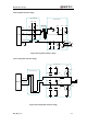
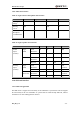
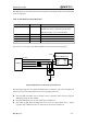
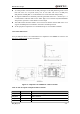
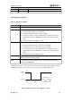
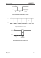
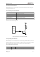
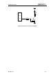
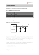
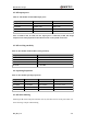
Table Of Contents
- Contents
- Table Index
- Figure Index
- 0. Revision history
- 1. Introduction
- 2. Product concept
- 3. Application interface
- 3.1. Pin
- 3.2. Operating modes
- 3.3. Power supply
- 3.4. Power on and down scenarios
- 3.5. Power saving
- 3.6. Summary of state transitions
- 3.7. RTC backup
- 3.8. Serial interfaces
- 3.9. Audio interfaces
- 3.10. SIM card interface
- 3.12. Behaviors of the RI
- 3.13. Network status indication
- 3.14. Operating status indication
- 4. Antenna interface
- 5. Electrical, reliability and radio characteristics
- 6. Mechanical dimensions
- 7. Storage and Manufacturing
- Appendix A: GPRS coding schemes
- Appendix B: GPRS multi-slot classes

M95 Hardware Design
M95_HD_V1.0 - 53 -
The SIM interface is powered from an internal regulator in the module. Both 1.8V and 3.0V SIM
Cards are supported.
Table 15: Pin definition of the SIM interface
The reference circuit using a 6-pin SIM card holder is illustrated as the following figure.
Module
22R
22R
22R
C707 10M006 512 2
SIM CARD
GND
SIM_VDD
SIM_RST
SIM_CLK
SIM_DATA
SIM_GND
100nF
VCC
RST
CLK
GND
VPP
IO
Figure 30: Reference circuit of the 6 pins SIM card
The following design rules can optimize the SIM interface performance and protect the SIM card
effectively. The rules should be taken into account in designing the circuit.
Place the SIM card holder close to module as close as possible. Ensure the trace length of
SIM signals keeps less than 200mm.
Keep the SIM signals far away from VBAT power and RF trace.
The width of SIM_VDD and SIM_GND trace is not less than 0.5mm. Place a bypass
capacitor close to SIM card power pin. The value of capacitor is less than 1uF.
Name
Pin
Function
SIM_VDD
27
Supply power for SIM Card. Automatic detection
of SIM card voltage. 3.0V±10% and 1.8V±10%.
Maximum supply current is around 10mA.
SIM_RST
28
SIM Card reset
SIM_DATA
29
SIM Card data I/O
SIM_CLK
30
SIM Card clock
SIM_GND
31
SIM Card ground