
User's Manual
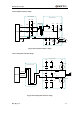
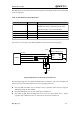
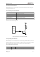
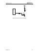
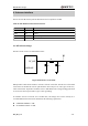
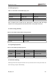
Table Of Contents
- Contents
- Table Index
- Figure Index
- 0. Revision history
- 1. Introduction
- 2. Product concept
- 3. Application interface
- 3.1. Pin
- 3.2. Operating modes
- 3.3. Power supply
- 3.4. Power on and down scenarios
- 3.5. Power saving
- 3.6. Summary of state transitions
- 3.7. RTC backup
- 3.8. Serial interfaces
- 3.9. Audio interfaces
- 3.10. SIM card interface
- 3.12. Behaviors of the RI
- 3.13. Network status indication
- 3.14. Operating status indication
- 4. Antenna interface
- 5. Electrical, reliability and radio characteristics
- 6. Mechanical dimensions
- 7. Storage and Manufacturing
- Appendix A: GPRS coding schemes
- Appendix B: GPRS multi-slot classes

M95 Hardware Design
M95_HD_V1.0 - 51 -
3.9.4. Earphone interface design
1
2
4
3
MIC2P
22uF
68R
33pF
GND GND
AGND
Close to Socket
33pF
AGND
33pF 10pF
GND
GND
GND
GND
AGND
Module
4.7uF
LOUDSPKP
Close to Module
GND
GND
GND
GND
10pF
33pF
33pF
10pF
Differential
layout
33pF
10pF
MIC2N
0R
Amphenol
9001-8905-050
Figure 28: Earphone interface design
3.9.5. Loud speaker interface design
LOUDSPKN
Differential layout
10pF
10pF
33pF
33pF
GND
GND
ESD ANTI
ESD ANTI
0R
0R
LOUDSPKP
GND
GND
GND GND
10pF
33pF
8 ohm
Close to Speaker
Module
Figure 29: Loud speaker interface design