
User's Manual
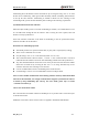
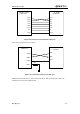
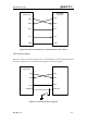
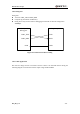
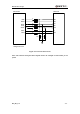
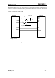
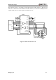
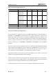
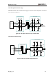
Table Of Contents
- Contents
- Table Index
- Figure Index
- 0. Revision history
- 1. Introduction
- 2. Product concept
- 3. Application interface
- 3.1. Pin
- 3.2. Operating modes
- 3.3. Power supply
- 3.4. Power on and down scenarios
- 3.5. Power saving
- 3.6. Summary of state transitions
- 3.7. RTC backup
- 3.8. Serial interfaces
- 3.9. Audio interfaces
- 3.10. SIM card interface
- 3.12. Behaviors of the RI
- 3.13. Network status indication
- 3.14. Operating status indication
- 4. Antenna interface
- 5. Electrical, reliability and radio characteristics
- 6. Mechanical dimensions
- 7. Storage and Manufacturing
- Appendix A: GPRS coding schemes
- Appendix B: GPRS multi-slot classes

M95 Hardware Design
M95_HD_V1.0 - 48 -
3.9. Audio interfaces
The module provides two analogy input channels and three analogy output channels.
Table 11: Pin definition of Audio interface
AIN1 and AIN2 can be used for input of microphone and line. An electret microphone is usually
used. AIN1 and AIN2 are both differential input channels.
AOUT1 is used for output of the receiver and speaker. This channel is typically used for a receiver
built into a handset. AOUT1 channel is a differential channel. It only supports voice path. If it is
used as a speaker, an amplifier should be employed.
AOUT2 is used for loud speaker output as it is embedded an amplifier of class AB whose
maximum drive power is 800mW. AOUT2 is a differential channel. Immediately playing Melody
or Midi ring tone for incoming call is available in AOUT2.
AOUT2 also can be used for output of earphone, which can be used as a single-ended channel.
LOUDSPKP and AGND can establish a pseudo differential mode.
These two audio channels can be swapped by “AT+QAUDCH” command. For more details,
please refer to document [1].
Use AT command “AT+QAUDCH” to select audio channel:
0--AIN1/AOUT1, the default value is 0.
2--AIN2/AOUT2
For each channel, customer can use AT+QMIC to adjust the input gain level of microphone.
Customer can also use “AT+CLVL” to adjust the output gain level of receiver and speaker.
“AT+QECHO” is used to set the parameters for echo cancellation control. “AT+QSIDET” is used
to set the side-tone gain level. For more details, please refer to document [1].
Interface
Name
Pin
Function
AIN1/AOUT1
MIC1P
4
Channel one of Microphone positive input
MIC1N
5
Channel one of Microphone negative input
SPK1N
6
Channel one of Audio negative output
SPK1P
7
Channel one of Audio positive output
AIN2/AOUT2
MIC2P
2
Channel two of Microphone positive input
MIC2N
3
Channel two of Microphone negative input
AGND
1
Cooperate with LOUDSPKP
LOUDSPKP
9
Channel two of Audio positive output
LOUDSPKN
8
Channel two of Audio negative output