
User's Manual
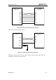
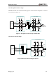
Table Of Contents
- Contents
- Table Index
- Figure Index
- 0. Revision history
- 1. Introduction
- 2. Product concept
- 3. Application interface
- 3.1. Pin
- 3.2. Operating modes
- 3.3. Power supply
- 3.4. Power on and down scenarios
- 3.5. Power saving
- 3.6. Summary of state transitions
- 3.7. RTC backup
- 3.8. Serial interfaces
- 3.9. Audio interfaces
- 3.10. SIM card interface
- 3.12. Behaviors of the RI
- 3.13. Network status indication
- 3.14. Operating status indication
- 4. Antenna interface
- 5. Electrical, reliability and radio characteristics
- 6. Mechanical dimensions
- 7. Storage and Manufacturing
- Appendix A: GPRS coding schemes
- Appendix B: GPRS multi-slot classes

M95 Hardware Design
M95_HD_V1.0 - 47 -
The following picture is an example of connection between module and PC. A RS_232 level
shifter IC or circuit must be inserted between module and PC, since these three UART ports don’t
support the RS_232 level, while support the CMOS level only.
9
8
7
6
5
4
3
2
1
15
14
8
9
11
12
5
7
6
10
4
26
2
27
13
18
20
21
16
17
19
22
23
24
3
1
25
28
GND
TO PC serial port
SP3238
3V
GND
GND
T5OUT
/SHUTDOWN
V+
GND
V-
VCC
T4OUT
T2OUT
T3OUT
T1OUT
R3IN
R2IN
R1IN
/STATUS
3V
ONLINE
R1OUT
R2OUT
R3OUT
/R1OUT
GND
T5IN
T4IN
T3IN
T2IN
T1IN
C2+
C2-
C1-
C1+
MODULE
RXD
DTR
RTS
RI
CTS
TXD
DCD
Figure 25: RS232 level match circuit