
User's Manual
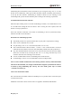
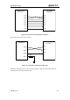
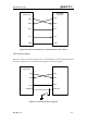
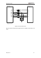
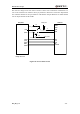
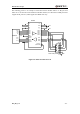
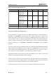
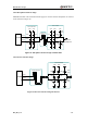
Table Of Contents
- Contents
- Table Index
- Figure Index
- 0. Revision history
- 1. Introduction
- 2. Product concept
- 3. Application interface
- 3.1. Pin
- 3.2. Operating modes
- 3.3. Power supply
- 3.4. Power on and down scenarios
- 3.5. Power saving
- 3.6. Summary of state transitions
- 3.7. RTC backup
- 3.8. Serial interfaces
- 3.9. Audio interfaces
- 3.10. SIM card interface
- 3.12. Behaviors of the RI
- 3.13. Network status indication
- 3.14. Operating status indication
- 4. Antenna interface
- 5. Electrical, reliability and radio characteristics
- 6. Mechanical dimensions
- 7. Storage and Manufacturing
- Appendix A: GPRS coding schemes
- Appendix B: GPRS multi-slot classes

M95 Hardware Design
M95_HD_V1.0 - 42 -
TXD
RXD
RTS
CTS
DTR
DCD
RI
TXD
RXD
RTS
CTS
DTR
DCD
RI
Module (DCE)
PC (DTE)
UART port
UART Port
GND GND
Figure 18: Connection of all functional UART port
Three lines connection is shown as below.
Host(DTE)
Controller
TXD
RXD
GND
Module(DCE)
TXD
RXD
GND
UART Port
RTS
0R
Figure 19: Connection of three lines UART port
UART Port with hardware flow control is shown as below. This connection will enhance the
reliability of the mass data communication.