
User's Manual
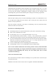
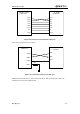
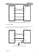
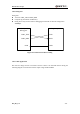
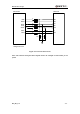
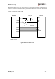
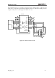
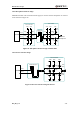
Table Of Contents
- Contents
- Table Index
- Figure Index
- 0. Revision history
- 1. Introduction
- 2. Product concept
- 3. Application interface
- 3.1. Pin
- 3.2. Operating modes
- 3.3. Power supply
- 3.4. Power on and down scenarios
- 3.5. Power saving
- 3.6. Summary of state transitions
- 3.7. RTC backup
- 3.8. Serial interfaces
- 3.9. Audio interfaces
- 3.10. SIM card interface
- 3.12. Behaviors of the RI
- 3.13. Network status indication
- 3.14. Operating status indication
- 4. Antenna interface
- 5. Electrical, reliability and radio characteristics
- 6. Mechanical dimensions
- 7. Storage and Manufacturing
- Appendix A: GPRS coding schemes
- Appendix B: GPRS multi-slot classes

M95 Hardware Design
M95_HD_V1.0 - 41 -
Autobauding allows the module to detect the baud rate by receiving the string “AT” or “at” from
the host or PC automatically, which gives module flexibility without considering which baud rate
is used by the host controller. Autobauding is enabled in default. To take advantage of the
autobauding mode, special attention should be paid according to the following requirements:
Synchronization between DTE and DCE:
When DCE (the module) powers on and the autobauding is enabled, it is recommended to wait 2
to 3 seconds before sending the first AT character. After receiving the “OK” response, DTE and
DCE are correctly synchronized.
If the host controller needs URC in the mode of autobauding, it must be synchronized firstly.
Otherwise the URC will be discarded.
Restrictions on autobauding operation
The UART port has to be operated at 8 data bits, no parity and 1 stop bit (factory setting).
The A/ and a/ commands can’t be used.
Only the strings “AT” or “at” can be detected (neither “At” nor “aT”).
The Unsolicited Result Codes like "RDY", "+CFUN: 1" and "+CPIN: READY” will not be
indicated when the module is turned on with autobauding enabled and not be synchronized.
Any other Unsolicited Result Codes will be sent at the previous baud rate before the module
detects the new baud rate by receiving the first “AT” or “at” string. The DTE may receive
unknown characters after switching to new baud rate.
It is not recommended to switch to autobauding from a fixed baud rate.
If autobauding is active it is not recommended to switch to multiplex mode
Note: To assure reliable communication and avoid any problems caused by undetermined baud
rate between DCE and DTE, it is strongly recommended to configure a fixed baud rate and save
it instead of using autobauding after start-up. For more details, please refer to Section
“AT+IPR” in document [1].
3.8.1.2. The connection of UART
The connection between module and host via UART port is very flexible. Three connection styles
are illustrated as below.
UART Port connection is shown as below when it is applied in modulation-demodulation.